PS5 DualSense Disassembly Guide: Thumbstick Cap and Button Repair
On this page46
- PS5 DualSense disassembly and repair: a photo guide
- Identify the fault before opening the controller
- Before disassembly: update, reset and consider official service
- Tools, replacement parts and hardware compatibility
- Disassembly 1: release the black front trim
- Lift the trim evenly from both sides
- Protect the tabs beside the touchpad
- Remove the two lower shell screws
- Remove the L1 and R1 buttons
- Remove the screws beneath L1 and R1
- Disassembly 2: open the rear shell
- Work around the shell seam
- If the shell resists, check its attachment points
- Disconnect and lift out the battery
- Release the rear microphone from its holder
- Disconnect the rear microphone cable
- Remove the battery-holder screw
- Lift out the battery holder
- Disconnect the ribbon cables needed to lift the board
- Disconnect the front microphone cable
- Remove the front microphone from the shell
- Disassembly 3: lift the motherboard
- Check the thumbsticks if the board will not lift
- Replace the thumbstick cap, not the joystick module
- Button repair 1: release the touchpad-area fasteners
- Lift the internal frame
- Keep the clear plastic piece and screws organized
- Separate the plate from the front shell
- Inspect and replace the conductive button membrane
- Reassembly 1: rebuild the front assembly
- Route the touchpad ribbon through its opening
- Refit the clear plastic part
- Refit and secure the internal frame
- Return each screw to its original location
- Reassembly 2: refit the motherboard and cables
- Refit the front microphone
- Reconnect the ribbon cables evenly
- Secure the battery holder
- Refit the rear microphone
- Inspect the interior, then reconnect the battery
- Reassembly 3: close the rear shell
- Reinstall the four shell screws
- Refit L1, R1 and the front trim
- Checks after disassembly, repair and reassembly
- Frequently asked questions
- Official support and scope of this guide
PS5 DualSense disassembly and repair: a photo guide
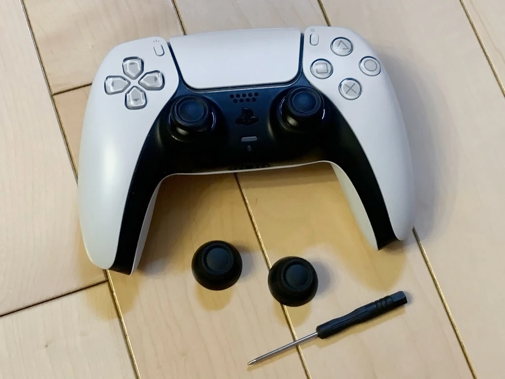
I opened my PS5 DualSense after the rubber on its left stick tore and the cross button became slow to return. These original photos document how I removed the covers, replaced the thumbstick cap and conductive button membrane, and put this controller back together.
The replaceable stick part in this guide is the plastic-and-rubber thumbstick cap. It is not the soldered analog joystick module that can cause stick drift. Identify the fault before buying parts or opening the controller.
The photos show the particular controller I repaired. Standard DualSense controllers have internal hardware revisions; parts and procedures are not identical across all versions. This is not a DualSense Edge guide.
Identify the fault before opening the controller
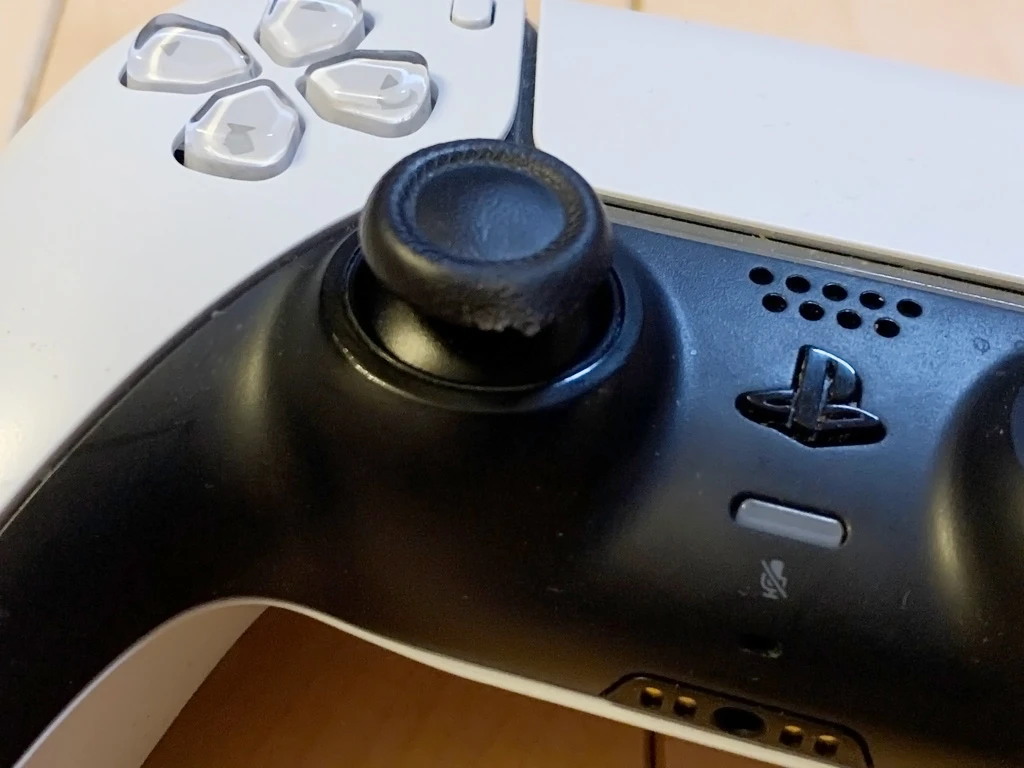
My controller had torn rubber on the left stick and a cross button with weak return. Surface damage, sticky buttons and unintended input are different faults.
| Symptom | What to check | Covered here? |
|---|---|---|
| Torn thumbstick rubber | Cap damage versus a damaged shaft or input fault | Cap replacement is illustrated |
| Button sticks or returns slowly | Debris, button fit and membrane condition | Access to the membrane is illustrated |
| Camera moves without touching the stick | Game settings, updates and reset | Replacing a cap normally does not fix drift |
| No charging or connection | USB cable, port and pairing | Start with official troubleshooting |
Before disassembly: update, reset and consider official service
For input or connection problems, try updating the controller software and resetting it before opening the shell. Turn off the PS5, disconnect USB, and hold the recessed reset button near the Sony logo on the controller back for at least five seconds. Reconnect to the PS5 using a USB cable that supports data and press the PS button. See PlayStation's official DualSense troubleshooting for the procedure.
Check warranty and service options with PlayStation Repairs before opening your controller. Service conditions vary by region. Stop if the battery is swollen, leaking or unusually hot; do not press, bend or puncture it.
Tools, replacement parts and hardware compatibility
Prepare a correctly fitting precision Phillips driver, plastic opening picks and a spudger, tweezers, and a tray for small parts. Do not push metal tools deep into shell seams. Photograph screw locations and cable orientation before removing them.
Starting a repair toolkit: iFixit Essential Electronics Toolkit
This basic set is a practical option if you need both a precision driver and tools for opening the case. The manufacturer lists Phillips bits including #00, a spudger, opening picks and tweezers. If you already own suitable tools, check their sizes before buying another set.
This article contains Amazon Associates links. As an Amazon Associate, Pamama earns from qualifying purchases. Shopping links lead to Amazon.co.jp in Japan.
This is a newly selected tool option, not the unbranded kit used in my original repair. I have not used this particular toolkit for the repair documented here.
Match replacement parts to your hardware revision
A listing marked “for PS5” is not enough. Compare your controller model and board revision, often identified by a BDM number, with the supplier's compatibility information. Button membranes must have the correct shape and locating points. Do not buy an unverified universal kit.
A replacement cap option appears in the thumbstick-cap section below. Check current price, availability and seller information on the Amazon product page before ordering.
Disassembly 1: release the black front trim
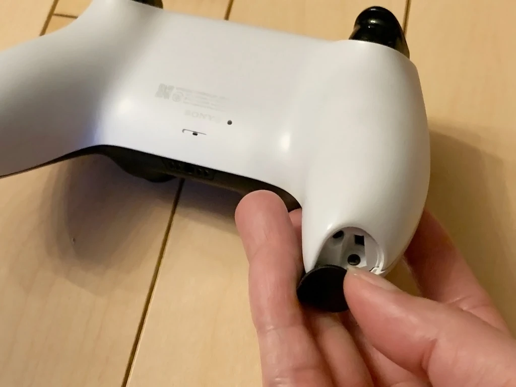
Turn the controller off and unplug USB. The battery is still connected internally at this stage: avoid pressing the PS button and keep metal tools away from the electronics.
Start at a lower grip edge of the black trim. Insert a plastic pick shallowly and release the left and right edges gradually. This piece is clipped in place; do not pull hard from one point.
Lift the trim evenly from both sides
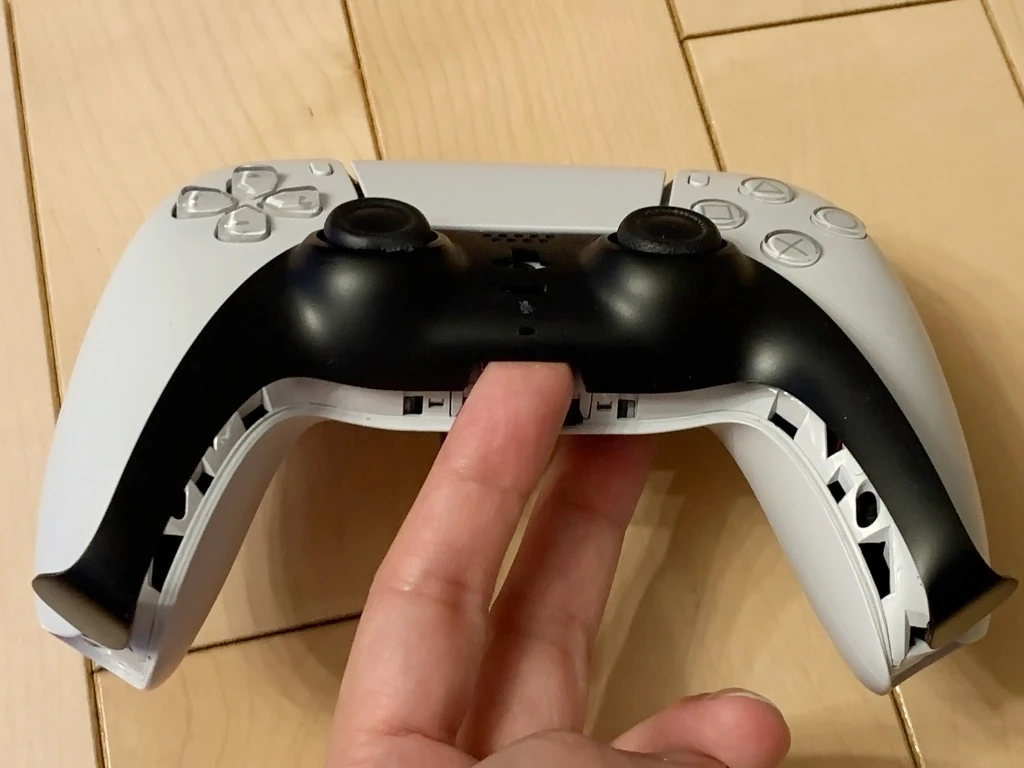
Once a lower edge is free, work along the trim and release its clips one at a time. Alternate sides. If a section resists, reposition the pick instead of pulling harder. Check the upper locating tabs before lifting the trim away.
Protect the tabs beside the touchpad
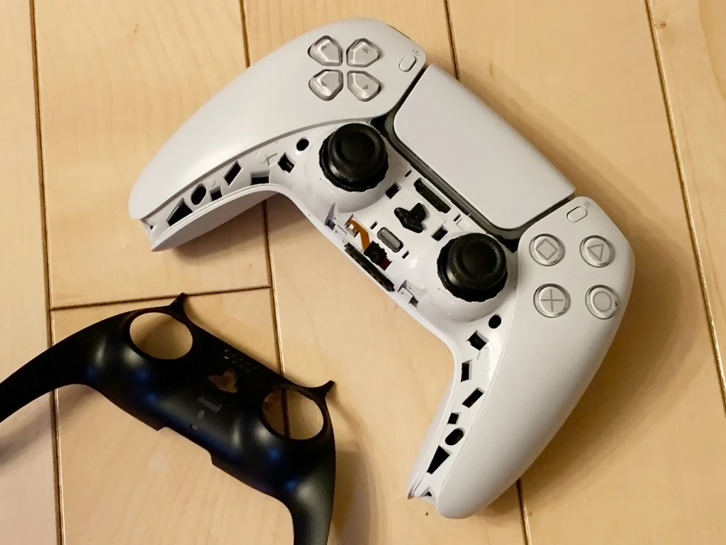
The trim has thin upper tabs near the touchpad. Do not bend the piece around those tabs as a pivot. Follow their direction when removing the trim, then put it somewhere the clips cannot be crushed.
Remove the two lower shell screws
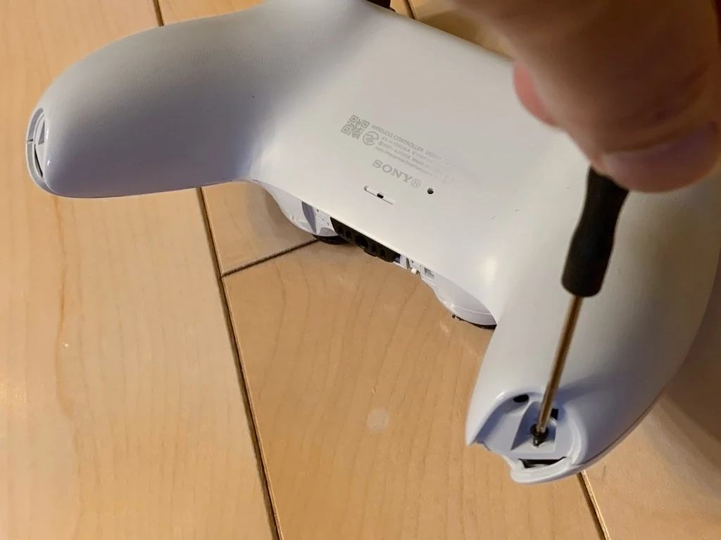
Remove the two Phillips screws exposed underneath the trim. Hold the screwdriver square to each screw to avoid stripping its head. Keep these screws together and label their location.
Remove the L1 and R1 buttons
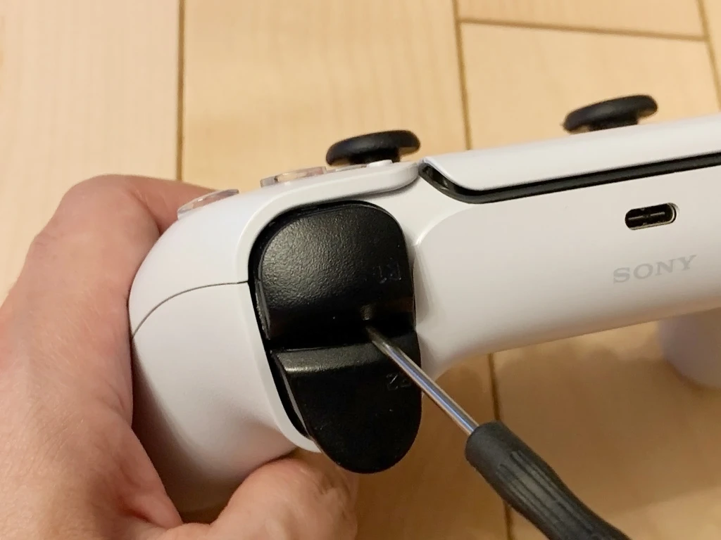
On the photographed controller, a plastic tool between each bumper and trigger released the L1 and R1 clips. Lift the bumper gradually. Avoid pressing on the trigger mechanism or its springs.
Remove the screws beneath L1 and R1
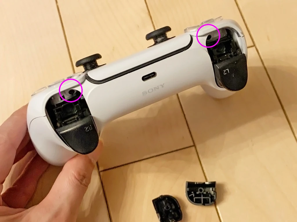
Remove one screw from beneath each bumper. Together with the two lower screws, these are the four outer shell screws on this controller. Check for any remaining fastener before separating the case.
Disassembly 2: open the rear shell
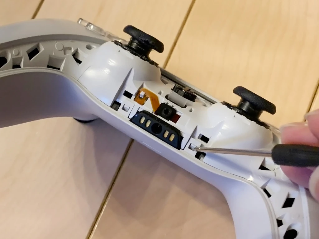
The rear shell is secured by clips as well as screws. Release the lower clips with a plastic tool. If the case does not separate, check for a missed screw or clip rather than pulling the halves apart.
Work around the shell seam
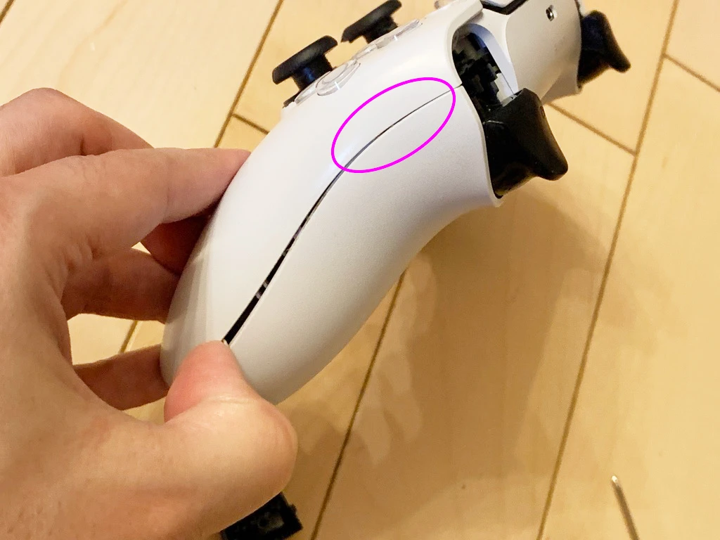
Keep the pick shallow and work around the seam in small movements. The upper areas shown in the photo can remain clipped. Release each attachment locally instead of inserting the tool deep into the controller.
If the shell resists, check its attachment points
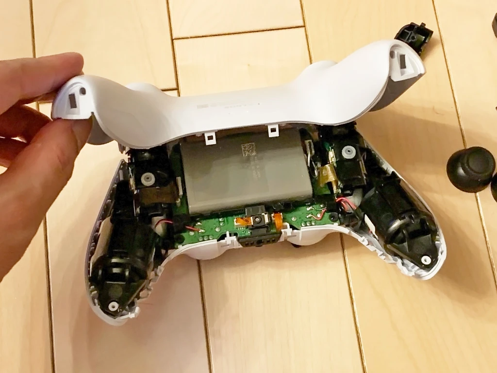
Stop and inspect the remaining clips and screw holes. On my controller the upper clips were the last to release after opening the lower edge. If the plastic starts to bend sharply or show stress whitening, reduce force and reassess.
Disconnect and lift out the battery
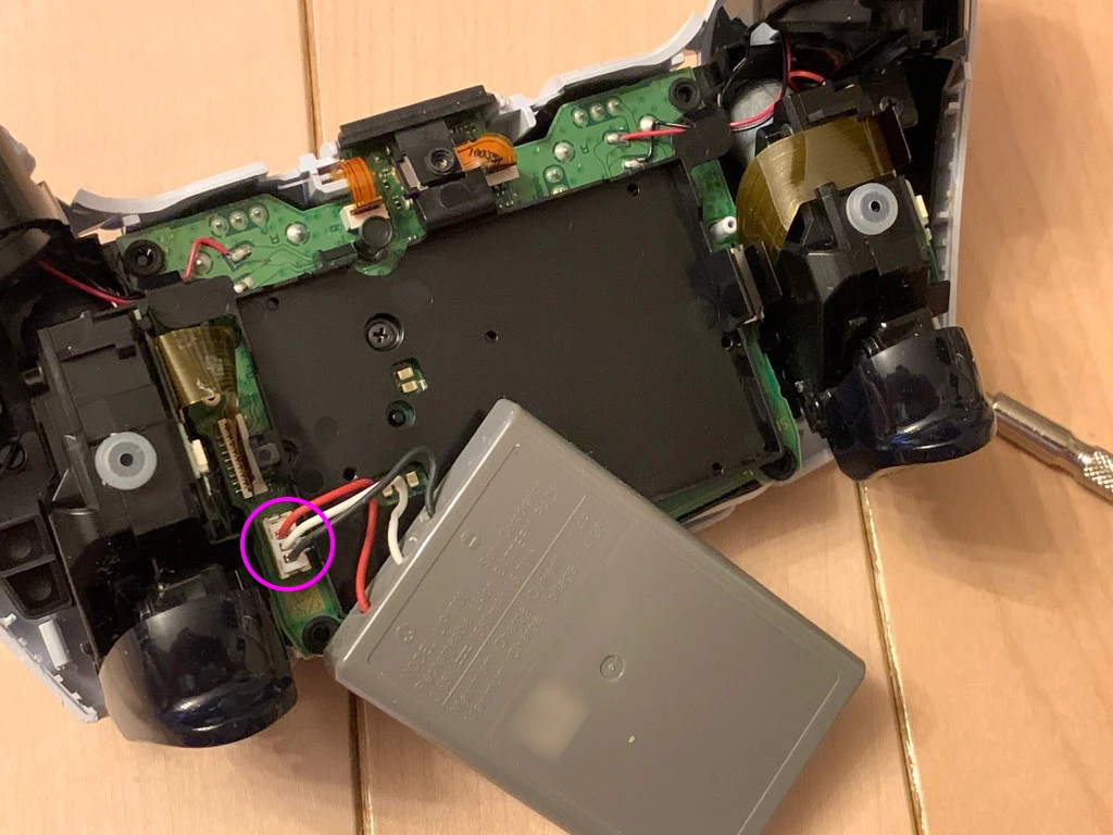
Once the shell is open, disconnect the battery before working on other connectors. Grip the plastic connector housing and check the socket's direction. Pulling on the wires alone can break them or damage the board socket.
Lift the battery without bending it or levering against it with a metal tool. Set it aside before handling microphone or ribbon-cable connections.
Release the rear microphone from its holder
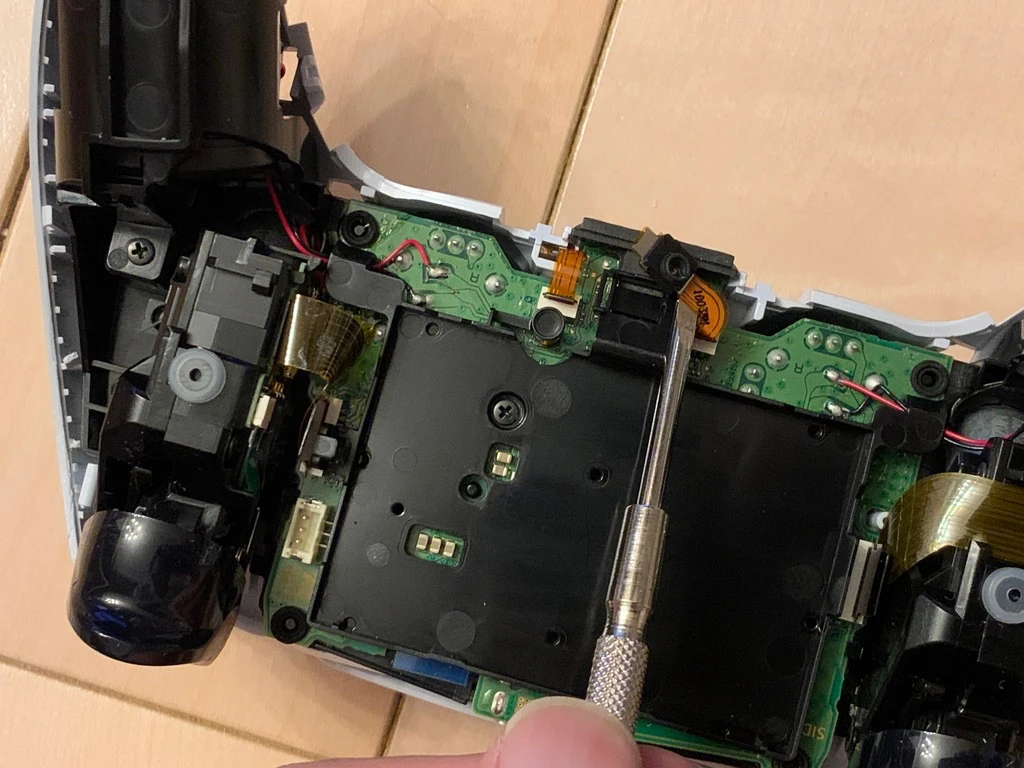
Photograph the rear microphone and its cable route before releasing it. On this controller it sits beside the battery holder. Lift the retained part gently without stretching the thin cable.
Disconnect the rear microphone cable
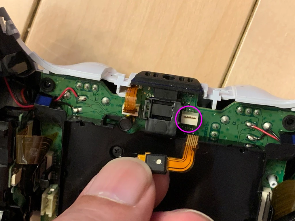
Identify the cable end at the board and withdraw it evenly without creasing it. Connector designs vary: if your version has a locking flap, identify and release that lock before pulling the cable.
Remove the battery-holder screw
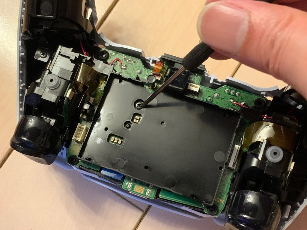
The photographed battery holder is secured by one Phillips screw. Remove it and check that no microphone or cable remains caught on the holder. Keep this screw separate from the shell screws.
Lift out the battery holder
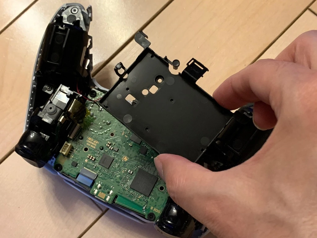
Lift the released holder away. If it catches, inspect the remaining cable route and attachment points. Photograph the newly exposed connections before unplugging them.
Disconnect the ribbon cables needed to lift the board
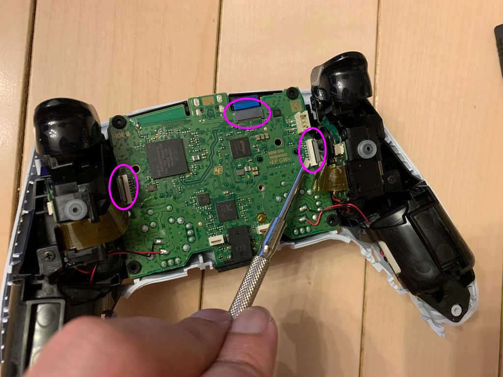
Disconnect the ribbon cables shown for this controller. The number, routing and connector design can differ by revision. Hold each reinforced end and check for a locking mechanism before withdrawing it.
Do not cut or desolder the vibration-motor wires for the cap or button-membrane work described here.
Disconnect the front microphone cable
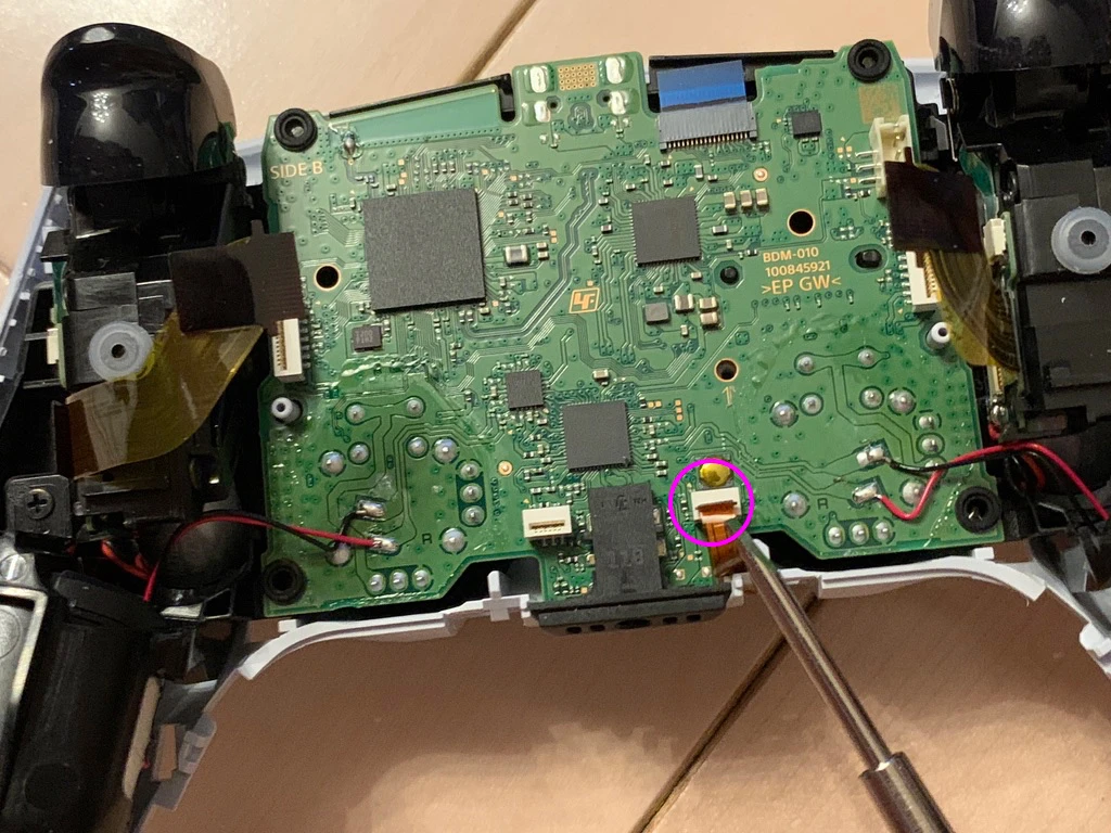
Identify the front microphone cable and release its board connection. Keep tools away from neighboring components and avoid folding the cable sharply.
Remove the front microphone from the shell
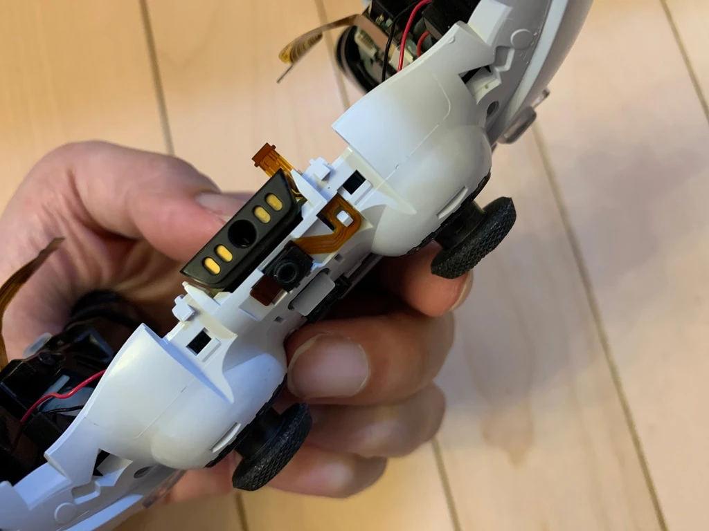
Record how the front microphone sits in the shell, including any rubber surround, then lift it out. Do not use its cable to pull the microphone free.
Disassembly 3: lift the motherboard
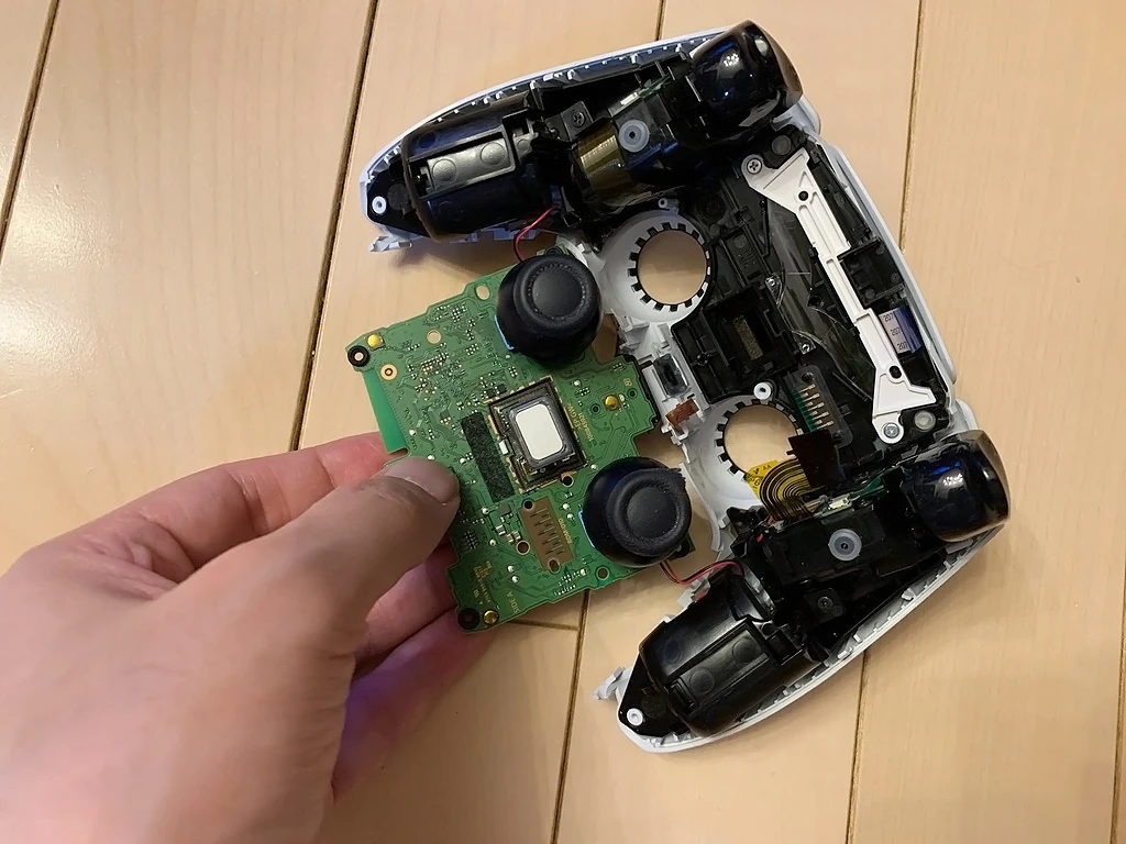
After releasing the necessary connections, lift the board carefully. Motor wires can still join it to the controller assembly. Support the board nearby and do not stretch those wires.
If a motherboard revision marking is visible, compare it with the replacement-part seller's compatibility information.
Check the thumbsticks if the board will not lift
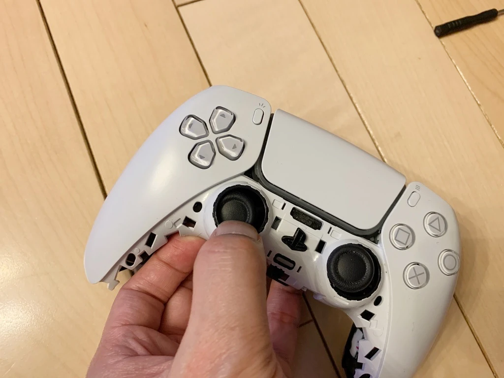
Check whether the caps catch in the front-shell openings. Gently guide them through as the board lifts. If a cable or fastener still holds the board, release that attachment rather than forcing the sticks through.
Replace the thumbstick cap, not the joystick module
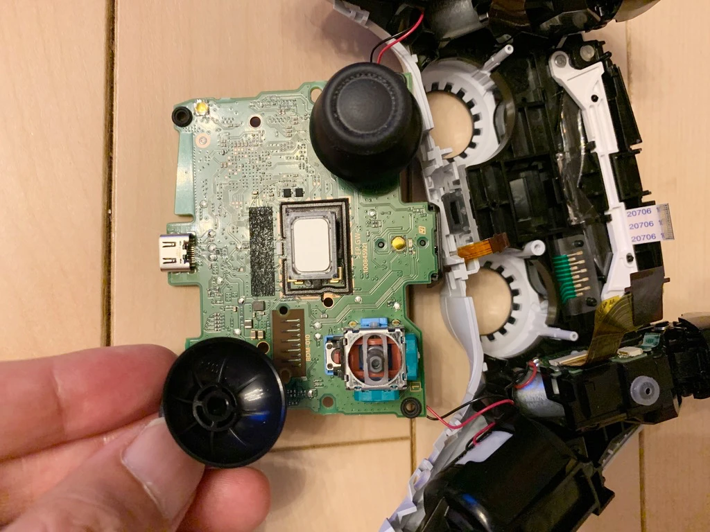
Support the board and pull the damaged cap straight along its shaft. Align the replacement with the shaft and press it into place. Check its height and clearance. If you are only replacing a cap, you do not need the deeper button-access steps that follow.
A torn cap and stick drift are different problems. Replacing the soldered joystick module in a standard DualSense requires desoldering and soldering, followed by input checks. That procedure is outside this photo guide. Consider an experienced repair service if the sensor module needs replacement.
Replacement option: eXtremeRate black thumbstick caps (JPF607). The manufacturer lists standard DualSense BDM-010 through BDM-060 compatibility. These replace the caps on the shafts after disassembly; they are not slip-on covers or electronic sensor modules. They do not repair drift. Check your model, material and package contents before ordering. This is a researched option, not a hands-on endorsement from my original repair.
Button repair 1: release the touchpad-area fasteners
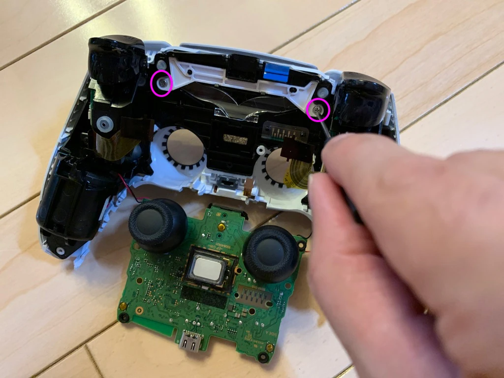
To reach the cross-button membrane, I continued into the front-shell assembly. On this controller, two silver screws release the internal frame near the touchpad. Skip this deeper disassembly if you only needed to replace a thumbstick cap.
Lift the internal frame
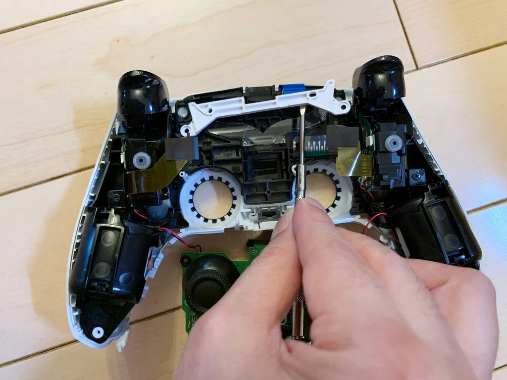
Lift the released frame gradually. Watch the thin plastic pieces and the touchpad cable underneath. If your fasteners differ from the photo, inspect them before continuing.
Keep the clear plastic piece and screws organized
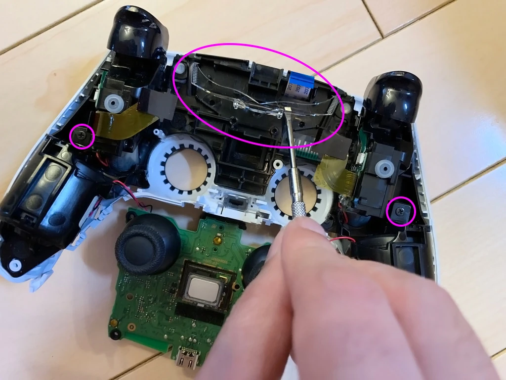
Remove the clear plastic part and the remaining screws shown. Record the orientation of small parts and store them separately. Do not reassemble the controller with a missing part simply omitted.
Separate the plate from the front shell
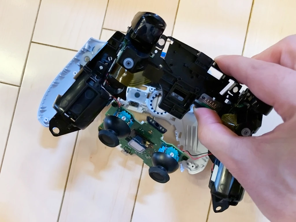
Lift the released plate away from the front shell while watching the touchpad cable route. This exposes the button membranes. Do not pull a cable through an opening by force.
Inspect and replace the conductive button membrane
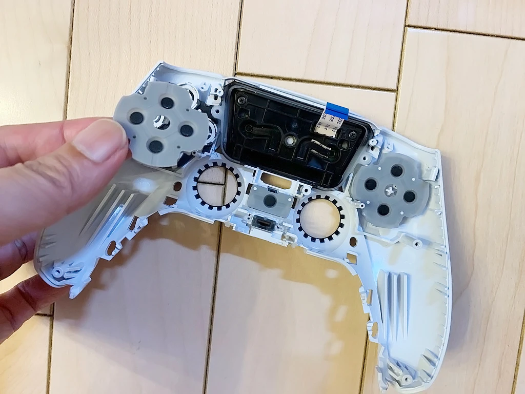
Inspect the membrane that returns the buttons, looking for tears, deformation, misalignment and debris. I replaced the damaged membrane in this controller with a matching part. The directional-pad and face-button membranes have different shapes; match their orientation and locating points.
Do not scrape the conductive surfaces or indiscriminately spray lubricant or contact cleaner into the assembly. A replacement membrane will not fix every possible button fault.
Reassembly 1: rebuild the front assembly
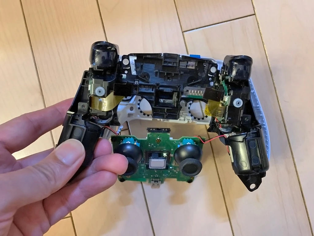
Check that every button and membrane is correctly seated, then return the plate to the front shell. Before installing the frame, check that buttons move freely and return without binding.
Route the touchpad ribbon through its opening
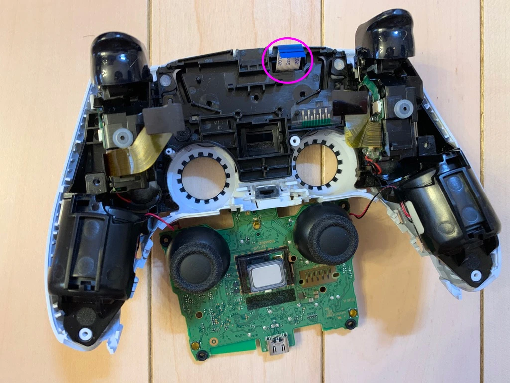
Route the touchpad ribbon through the plate opening as shown. Check both sides so the cable is not trapped beneath a plate or screw.
Refit the clear plastic part
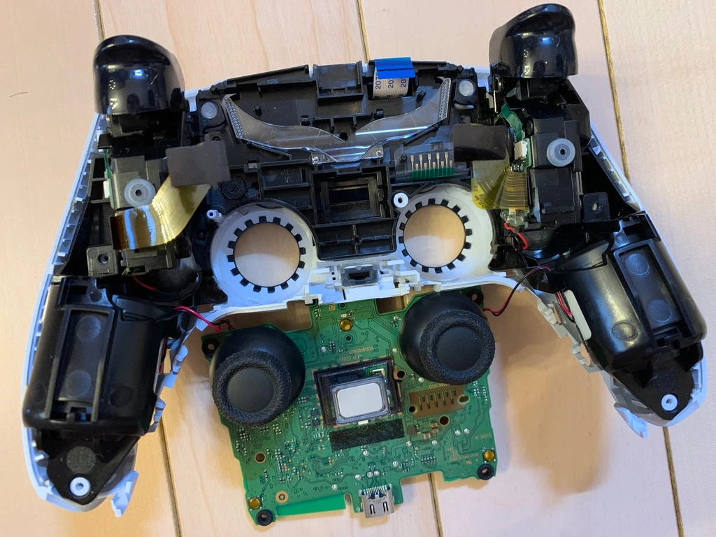
Return the clear plastic piece to its original position and orientation. Compare your disassembly photos if needed. If it needs excessive force, check that it is the right way up and correctly located.
Refit and secure the internal frame
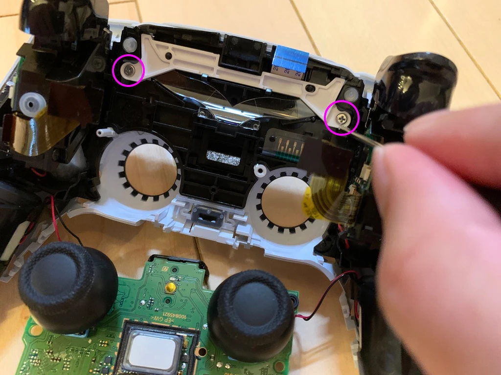
Locate the frame and reinstall its screws. Confirm that the touchpad cable and small parts remain correctly seated. Avoid overtightening screws that fasten into plastic.
Return each screw to its original location
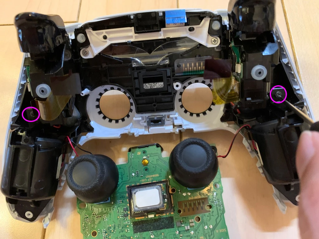
Use the screw groups and photos you made during disassembly. Return each screw to its original hole; do not substitute a longer screw for a shorter one.
Reassembly 2: refit the motherboard and cables
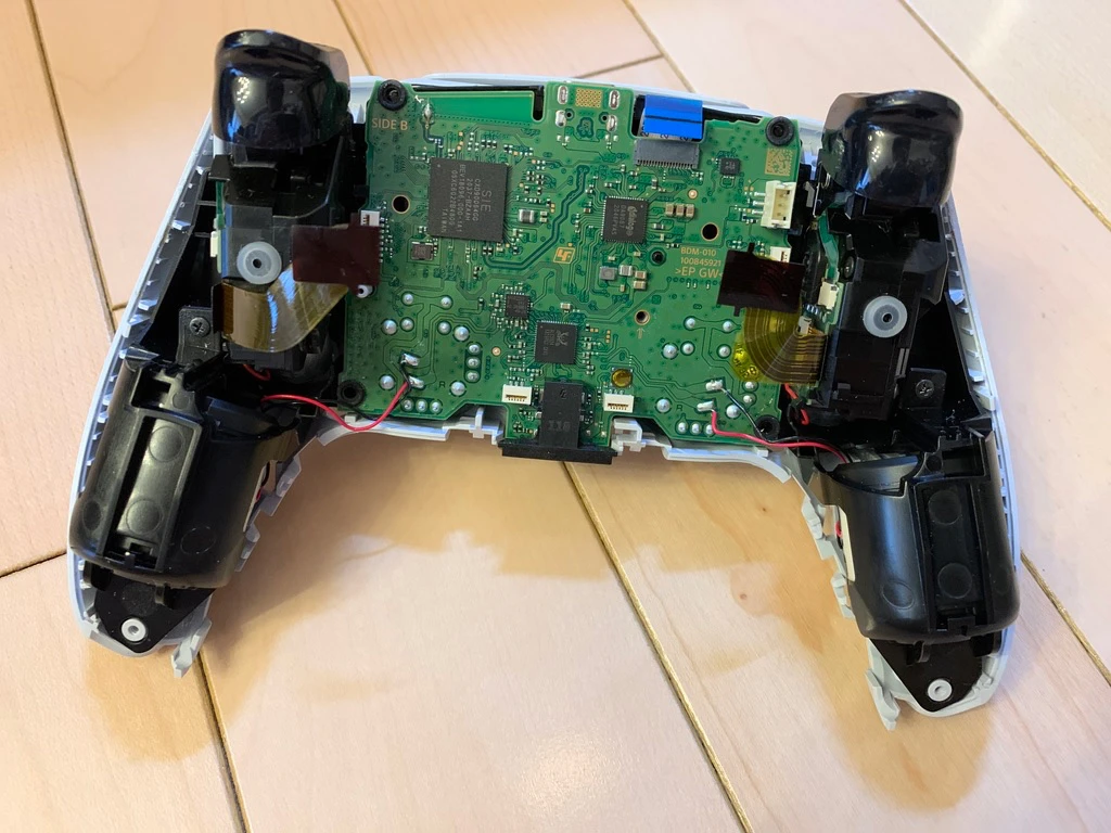
Turn the board back to its original orientation, guide the thumbstick caps through the front-shell openings and seat it. Keep motor wires and ribbon cables out from beneath the board.
Refit the front microphone
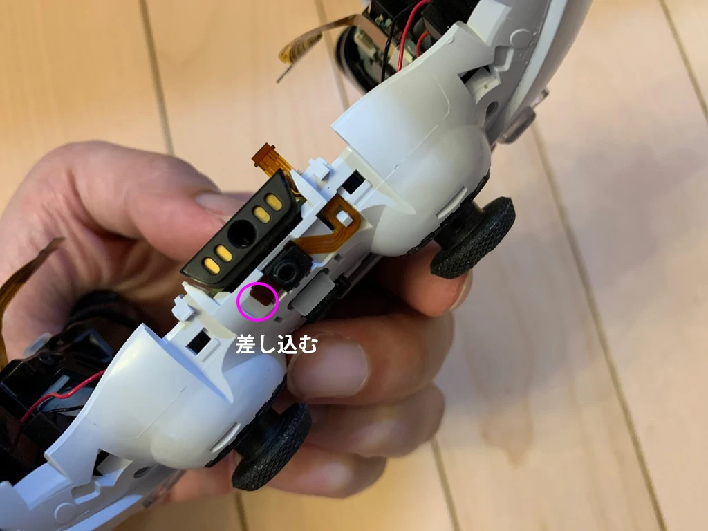
Seat the front microphone and its surround in their original orientation. Check that the cable follows its route and does not protrude into a shell seam or sit beneath the frame.
Reconnect the ribbon cables evenly
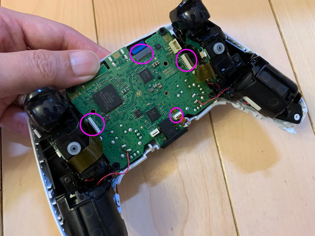
Check the contact orientation and hold each reinforced end. Insert it squarely to its proper depth, then close any connector lock. Inspect both edges for an uneven or partial insertion.
Secure the battery holder
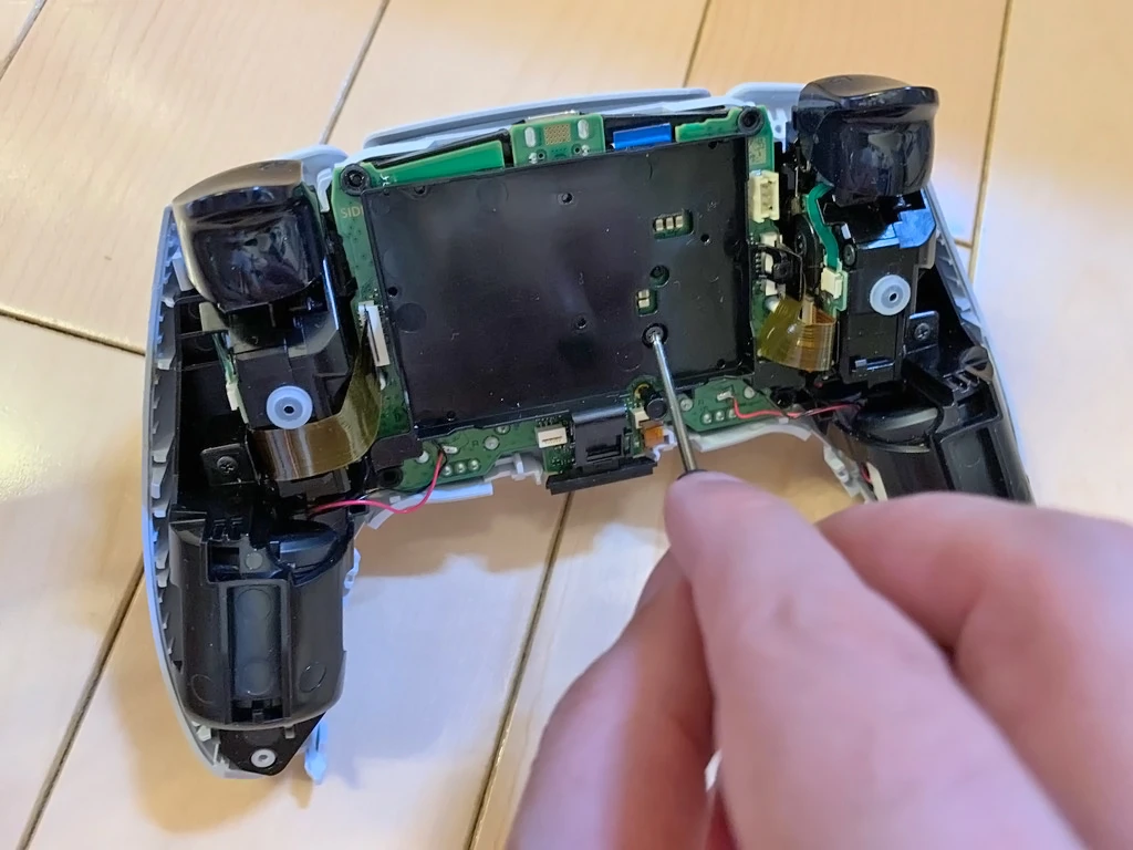
Check the cable routes, place the battery holder back and reinstall its screw. It should seat naturally without crushing any cable underneath.
Refit the rear microphone
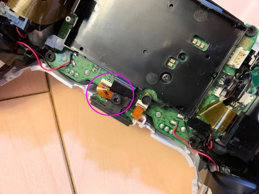
Return the rear microphone to its holder and reconnect its cable along the original route. Check its position and connection before putting the battery back.
Inspect the interior, then reconnect the battery
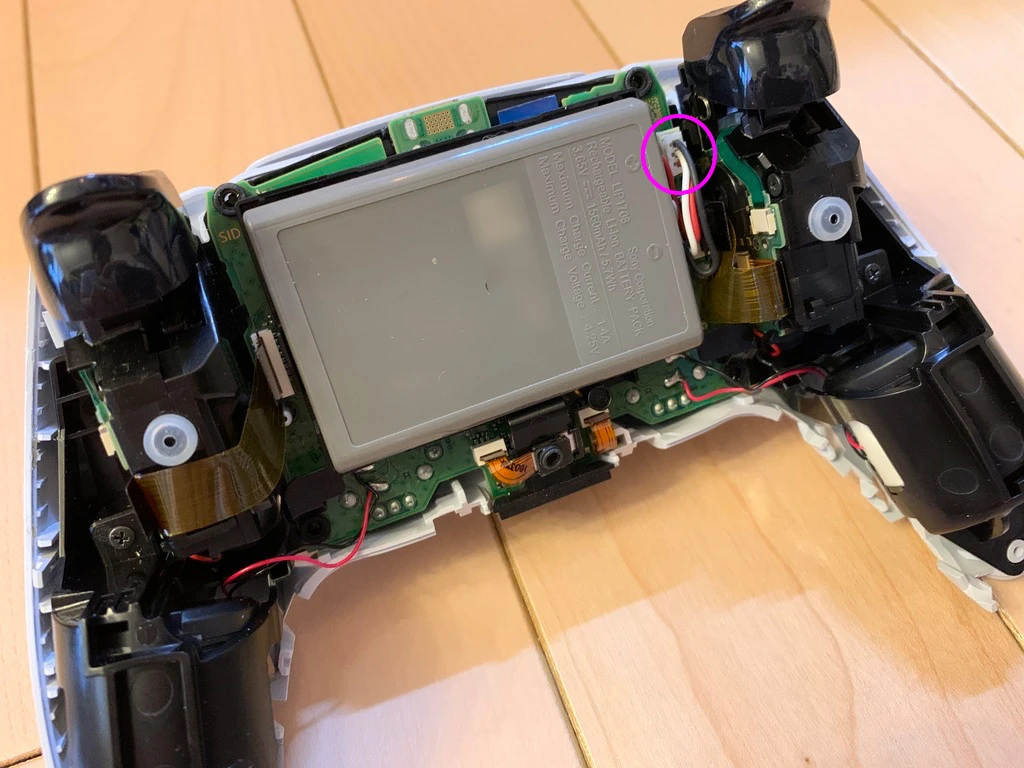
Check for loose screws, forgotten tools and trapped cables. Seat the battery and reconnect its plug in the correct orientation. Keep its wires away from shell clips and screw holes.
The controller is powered internally again. Do not touch electrical contacts or reconnect internal cables while it is powered.
Reassembly 3: close the rear shell
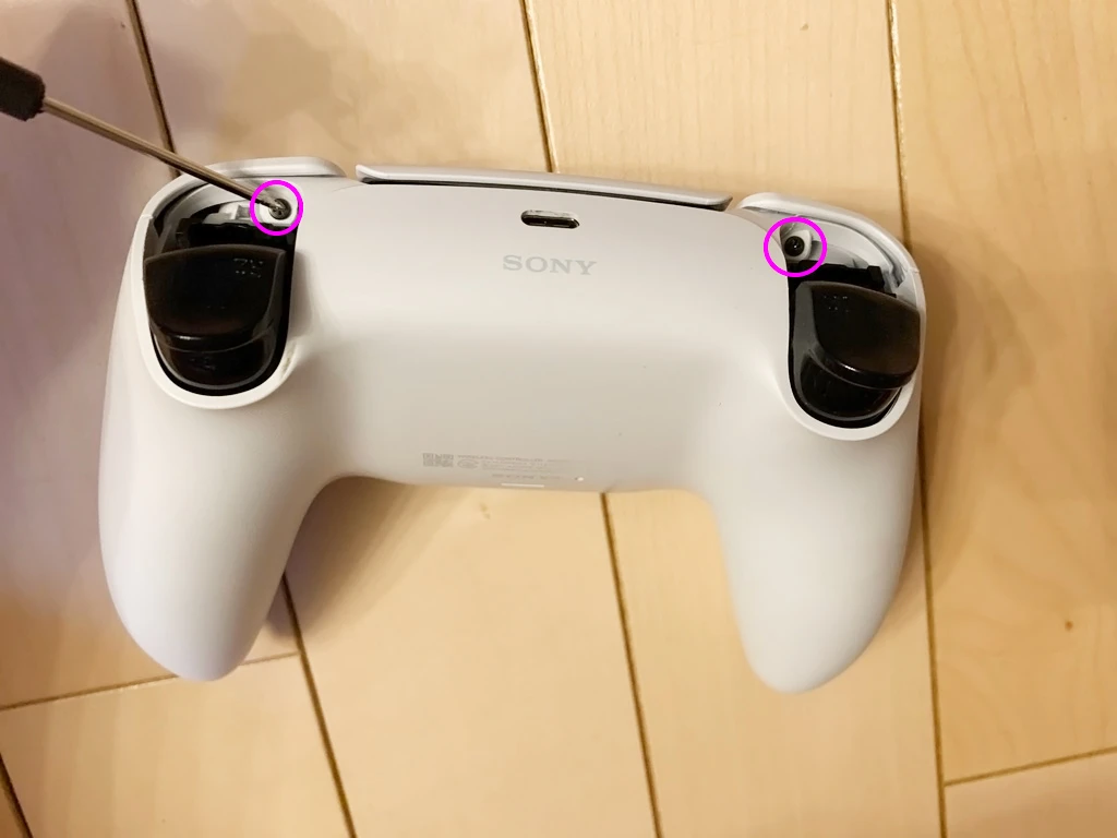
Align the rear shell and engage its clips in sequence. If it will not close, inspect the cable routes and seating of internal parts rather than forcing it shut. Disconnect the battery first if you need to work inside again.
Reinstall the four shell screws
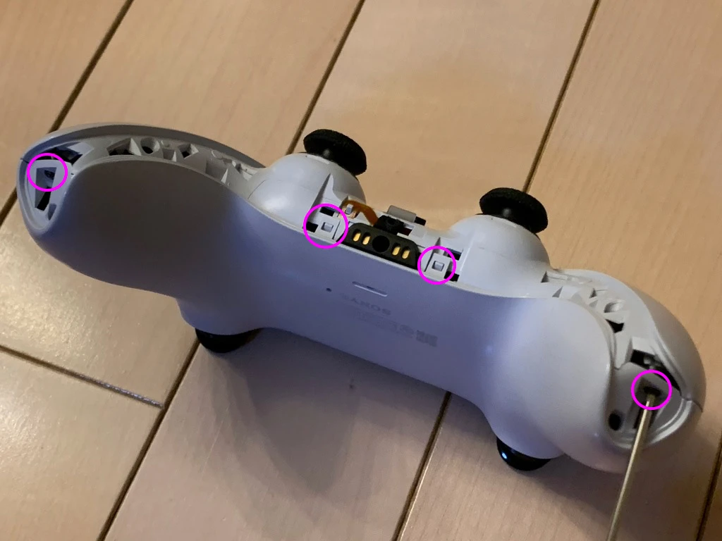
Return the two lower screws and the two beneath L1 and R1. The shell should already fit correctly; do not use screw tension to force a gap closed.
Refit L1, R1 and the front trim
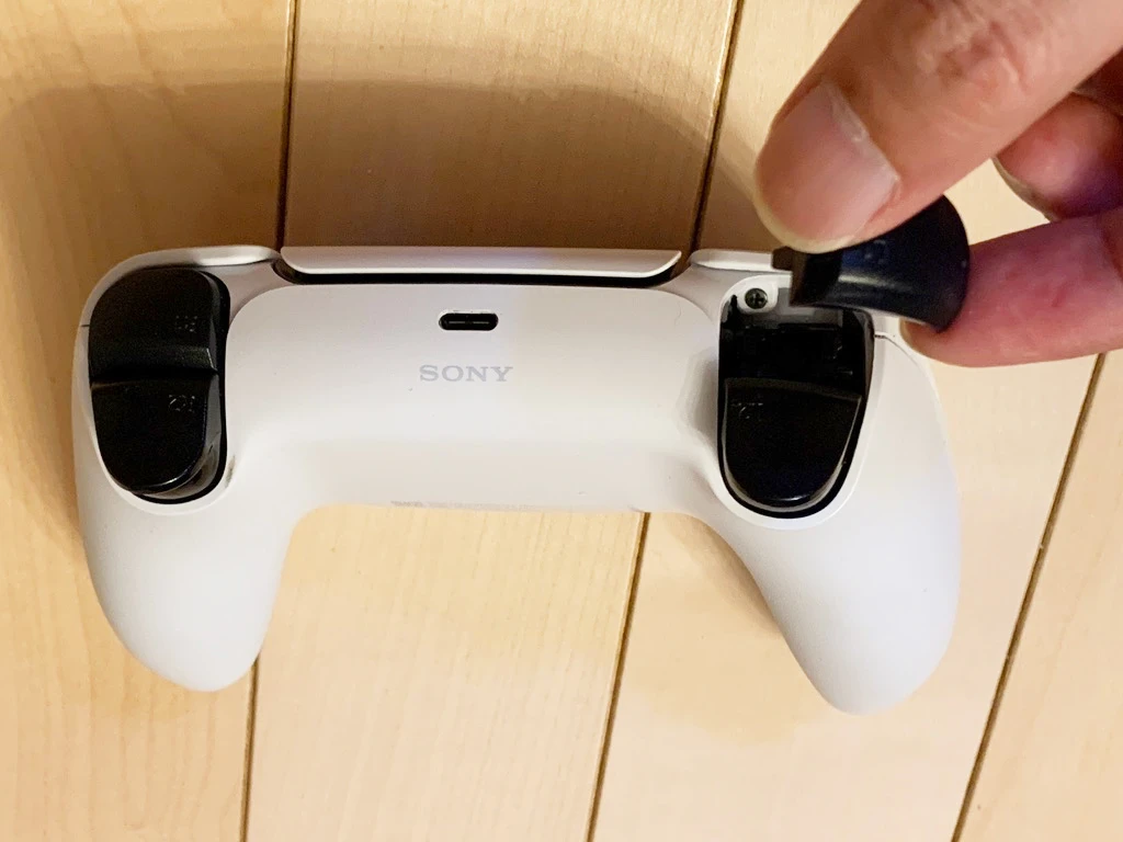
Align and refit the L1 and R1 bumpers without bending their clips. Check their travel and return. Align the upper tabs of the black trim, then engage its left and right edges.
Checks after disassembly, repair and reassembly
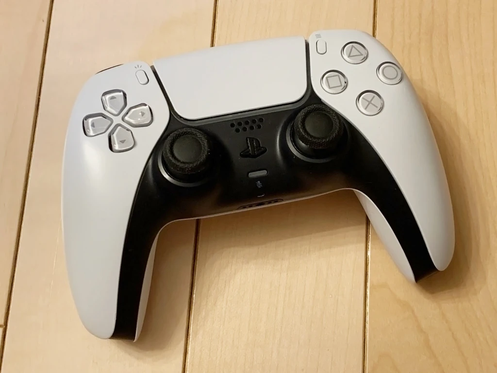
With the shell closed, check that every button returns freely and neither stick rubs against the case. Connect to the PS5 over USB and press the PS button.
- Test the face buttons, D-pad, bumpers, triggers and L3/R3 clicks.
- Move both sticks in every direction and check for unintended input at rest.
- Check the touchpad, PS, Create and Options buttons.
- Check charging, USB data, wireless connection, microphone, mute and vibration.
If a new fault appears after assembly, a loose cable or misplaced part may be responsible. Turn the controller off, unplug USB and disconnect the battery before inspecting the interior again.
Repair costs and service conditions change. Compare compatible parts, tools and the risk of additional damage rather than assuming a kit will be cheaper or cure drift. If replacement makes more sense, the Sony DualSense product page shows current Amazon Japan listings.
Replacement option: a genuine Sony DualSense (CFI-ZCT2J). Consider replacing the controller if parts and tools would cost too much, if you are not comfortable repairing it, or if you want a spare before starting. This listing is for a complete controller; it does not establish that its internal layout matches the unit in this guide. Check the seller, condition and warranty terms.
Frequently asked questions
Will replacing a thumbstick cap fix stick drift?
Usually not. This guide replaces a physically damaged cap. Persistent drift needs its own diagnosis and may require service or work on the soldered joystick module.
Will one repair kit fit every DualSense?
No universal fit should be assumed. Match the controller model, board revision and the parts maker's compatibility list. Standard DualSense and DualSense Edge parts are not interchangeable by default.
Can cleaning alone fix a sticky button?
It may help if debris is the cause. It cannot repair a torn membrane, deformed shell or faulty board. Do not spray liquids into the controller as a general cure.
What should I try without opening it?
For input or connection issues, check game settings, software updates, reset and reconnection. These steps cannot repair torn rubber or other physical damage.
Official support and scope of this guide
The photos show how I disassembled and reassembled my DualSense. Before buying replacement parts, match your controller model to the parts maker’s compatibility list. Use the official links below for connection, updates and repair service.
Official links checked on November 7, 2026.
Latest guides
12
PS5 DualSense Disassembly Guide: Thumbstick Cap and Button Repair
Updated article content.

FFXIV Areas
Updated guide information.

FFXIV Shops
Updated guide information.
FFXIV Duties | Dungeons, Trials & Raids
Updated guide information.

[FFXIV Patch 6.15] The Arkasodara Tribe Quests and New mount Hippo Cart added !
Updated images.

FFXIV This week & next week’s workshop schedules
Updated the key visual and thumbnails with enhanced images.

FFXIV Felicitous Favors
Updated the key visual and thumbnails with enhanced images.

FFXIV Workshop schedule planner
Updated the key visual and thumbnails with enhanced images.

FFXIV Living Memory Aether Currents
Updated the key visual and thumbnails with enhanced images.

FFXIV Heritage Found Aether Currents
Updated the key visual and thumbnails with enhanced images.

FFXIV Shaaloani Aether Currents
Updated the key visual and thumbnails with enhanced images.

FFXIV Yak T'el Aether Currents
Updated the key visual and thumbnails with enhanced images.